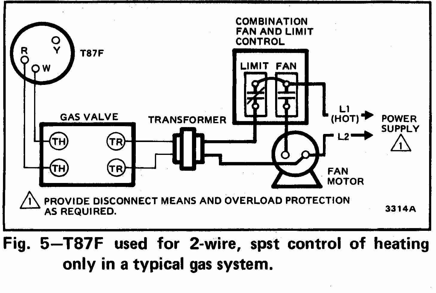
Wiring Thermostat Diagrams are essential tools for understanding and troubleshooting the electrical connections within a thermostat system. These diagrams provide a visual representation of how the various wires in a thermostat are connected to the HVAC system, allowing for proper installation and maintenance.
Why Wiring Thermostat Diagrams are Essential
- Ensure proper installation of thermostats
- Help troubleshoot electrical issues
- Provide guidance for wiring upgrades or replacements
Reading and Interpreting Wiring Thermostat Diagrams
When reading a wiring thermostat diagram, it is important to understand the symbols and color-coding used to represent different wires and components. Follow the key or legend provided on the diagram to identify each element correctly.
- Identify the power source and terminal connections
- Understand the function of each wire and component
- Follow the wiring path from the thermostat to the HVAC system
Using Wiring Thermostat Diagrams for Troubleshooting
Wiring thermostat diagrams are valuable tools for diagnosing and resolving electrical problems in a thermostat system. By referencing the diagram, you can identify faulty connections, broken wires, or incorrect installations that may be causing issues with the HVAC system.
- Check for continuity and proper voltage at each terminal
- Verify the correct wiring sequence and connections
- Compare the diagram with the actual wiring to locate discrepancies
Importance of Safety
Working with electrical systems can be dangerous, so it is crucial to prioritize safety when using wiring thermostat diagrams. Follow these safety tips and best practices to prevent accidents and injuries:
- Always turn off the power before working on any electrical connections
- Use insulated tools and equipment to avoid electric shocks
- Double-check all connections before restoring power to the system
- Seek professional help if you are unsure or uncomfortable with the task
Wiring Thermostat Diagram
Wiring Diagram For Ac Unit Thermostat

Thermostat Wiring Explained

How To Wire A Ac Thermostat

How To Wire A Thermostat Diagram
Guide to wiring connections for room thermostats

Honeywell Thermostat Wiring Diagram 6 Wire
