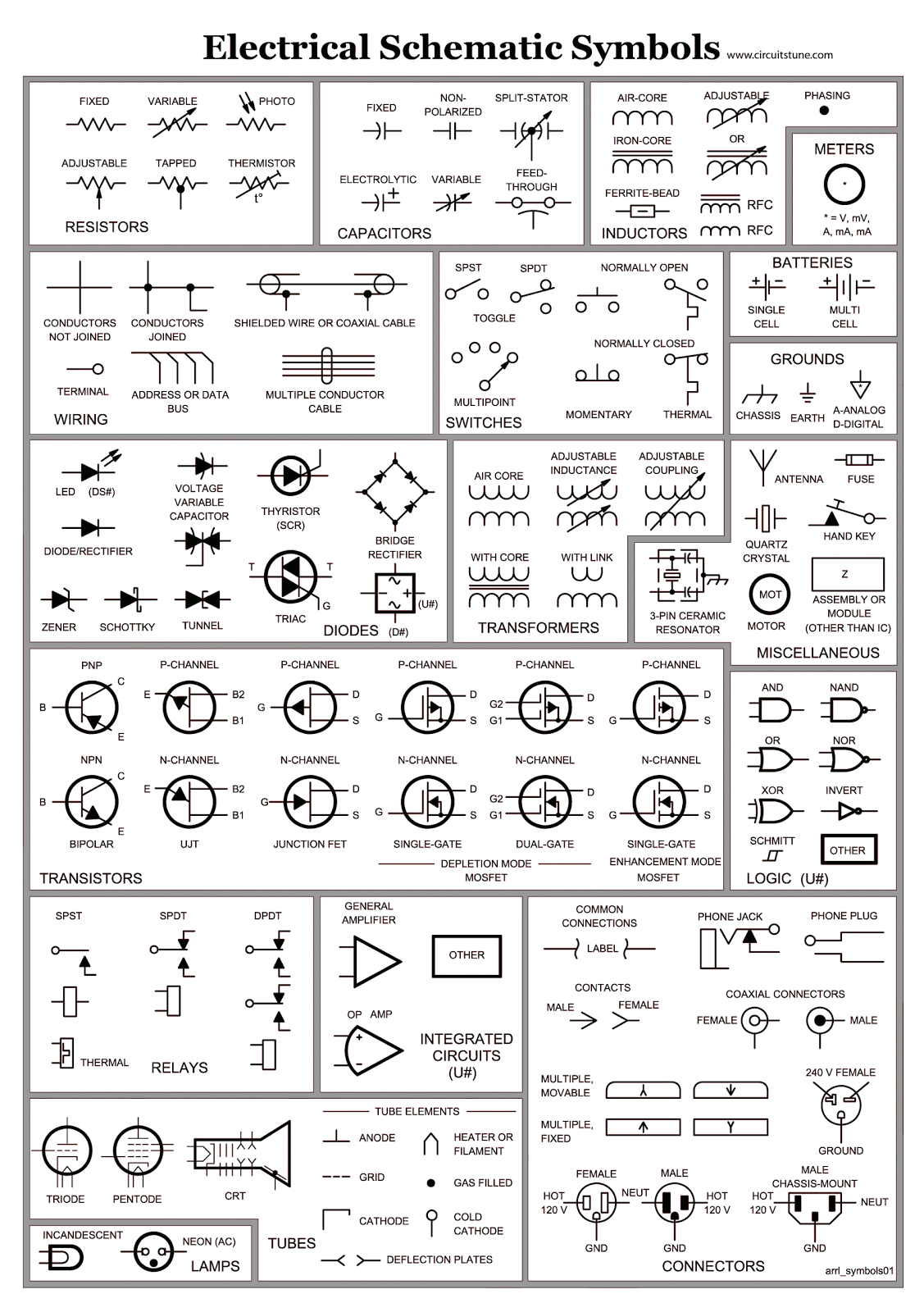
Wiring Schematics Symbols are essential in understanding the complex world of electrical systems. These symbols are used to represent various components and connections in electrical diagrams, making it easier for technicians to troubleshoot and repair electrical systems.
Why Wiring Schematics Symbols are essential
- Provide a standardized way to represent electrical components
- Help technicians understand the layout and connections of electrical systems
- Aid in troubleshooting electrical problems efficiently
- Ensure safety by providing clear instructions for proper wiring
How to read and interpret Wiring Schematics Symbols effectively
When reading wiring schematics symbols, it is important to familiarize yourself with the common symbols used in electrical diagrams. These symbols may vary slightly depending on the diagram, but some of the most common ones include:
- Resistor – Represents resistance in a circuit
- Switch – Controls the flow of electricity in a circuit
- Ground – Connects the circuit to the earth for safety
- Battery – Provides power to the circuit
How Wiring Schematics Symbols are used for troubleshooting electrical problems
By understanding and interpreting wiring schematics symbols, technicians can pinpoint the root cause of electrical issues quickly. They can follow the connections in the diagram to identify faulty components or wiring, making the troubleshooting process more efficient and effective.
Safety when working with electrical systems
When working with electrical systems and using wiring diagrams, it is crucial to prioritize safety. Here are some safety tips and best practices to keep in mind:
- Always turn off the power before working on any electrical system
- Use insulated tools to prevent electrical shock
- Avoid working on wet surfaces or in damp conditions
- Double-check your work to ensure all connections are secure and correct
Wiring Schematics Symbols
Basic Electrical Wiring Diagram Symbols

Electrical Schematic Symbols ~ CircuitsTune

All Electrical Schematic Symbols

Basic Wiring Diagram Symbols
.jpg)
How To Read Electrical Schematic Symbols

The Ultimate Guide to Understanding Wiring Schematic Symbols
