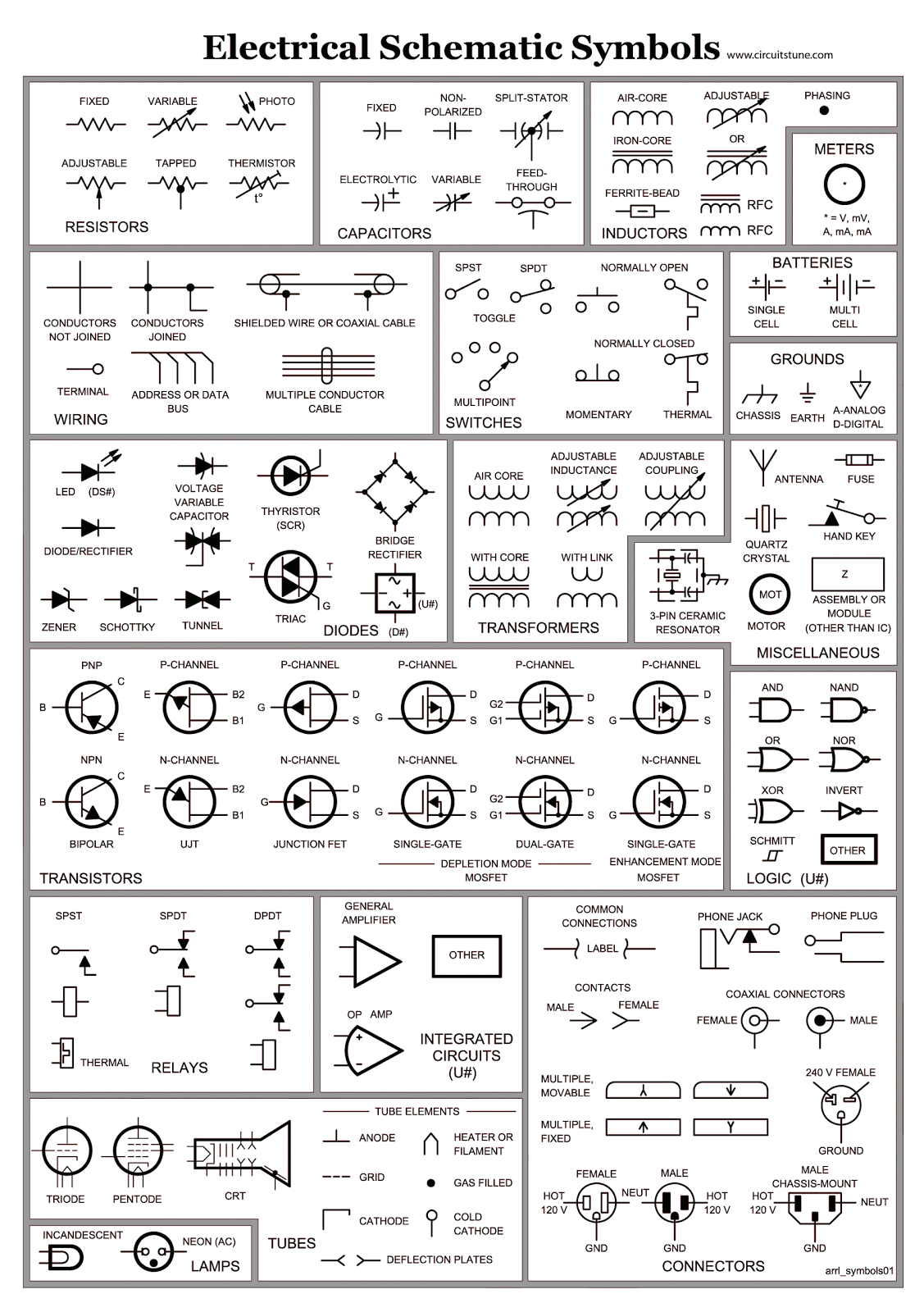
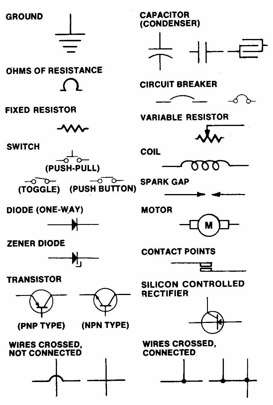
Wiring Schematic Symbols are essential for understanding and interpreting electrical diagrams used in various industries such as automotive, electronics, and construction. These symbols represent different components and connections in a circuit, allowing technicians and engineers to design, troubleshoot, and repair electrical systems efficiently.
Why Wiring Schematic Symbols are Essential
Wiring Schematic Symbols serve as a universal language for electrical engineers and technicians to communicate and understand complex electrical diagrams. They provide a visual representation of components such as resistors, capacitors, switches, and wires, making it easier to design and analyze circuits.
- Facilitate communication and collaboration among professionals in the electrical industry
- Ensure consistency and accuracy in electrical designs and schematics
- Streamline troubleshooting and repair processes by identifying components quickly
- Enhance safety by clearly indicating the function and connections of each component
How to Read and Interpret Wiring Schematic Symbols Effectively
Understanding Wiring Schematic Symbols requires knowledge of basic electrical theory and familiarity with common symbols used in circuit diagrams. By following these steps, you can effectively read and interpret wiring schematic symbols:
- Familiarize yourself with common symbols for components such as resistors, capacitors, diodes, and transistors
- Refer to a legend or key that explains the meaning of each symbol in the schematic
- Follow the flow of the circuit from the power source to the load to understand how components are connected
- Use color coding and labeling to differentiate between different types of wires and connections
Using Wiring Schematic Symbols for Troubleshooting Electrical Problems
Wiring Schematic Symbols play a crucial role in diagnosing and troubleshooting electrical problems in circuits and systems. By analyzing the schematic diagram and identifying faulty components or connections, technicians can efficiently pinpoint and resolve issues. Here are some ways to use wiring schematic symbols for troubleshooting:
- Compare the actual circuit with the schematic to identify discrepancies or missing components
- Use a multimeter to test components and verify their functionality
- Trace the flow of electricity through the circuit to locate potential areas of failure
- Consult technical manuals and resources to interpret complex symbols and diagrams
Importance of Safety When Working with Electrical Systems
When working with electrical systems and using wiring diagrams, safety should be a top priority to prevent accidents and injuries. Follow these safety tips and best practices to ensure a safe working environment:
- Always turn off the power supply before working on electrical circuits
- Use appropriate personal protective equipment (PPE) such as insulated gloves and safety goggles
- Avoid working alone on electrical projects and seek assistance if needed
- Label and organize wires and components to prevent confusion and misconnections
Wiring Schematic Symbols
Electrical Schematic Symbols ~ CircuitsTune

Printable Electrical Schematic Symbols Chart Pdf

Common Electrical Symbols Wiring Diagram

All Electrical Schematic Symbols

How To Use Schematics On Basic Electronics
.jpg)
Electrical Schematic Symbols | The Simplest Circuit
