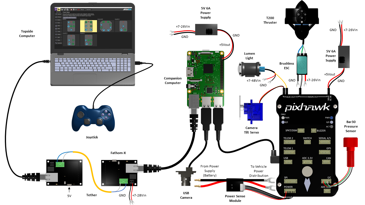
Wiring Connection Diagrams are essential tools for anyone working with electrical systems, whether it be in a vehicle, a piece of machinery, or a building. These diagrams provide a visual representation of the connections between various components in a system, helping to ensure that the wiring is done correctly and that everything is functioning as it should. Understanding how to read and interpret these diagrams is crucial for anyone working in the field of mechanics or electrical engineering.
Why are Wiring Connection Diagrams essential?
- Ensure proper wiring connections
- Prevent electrical malfunctions
- Improve efficiency in troubleshooting
- Ensure safety for both equipment and personnel
How to read and interpret Wiring Connection Diagrams effectively
When looking at a Wiring Connection Diagram, it’s important to first understand the symbols used to represent different components. Some common symbols include lines for wires, circles for connections, and squares for components such as switches or relays. It’s also important to follow the flow of the diagram from one component to another, ensuring that all connections are made correctly.
Using Wiring Connection Diagrams for troubleshooting electrical problems
- Identify potential issues with wiring connections
- Locate faulty components or connections
- Follow the diagram to trace the flow of electricity
- Compare actual wiring to diagram to identify discrepancies
Importance of safety when working with electrical systems
When working with electrical systems and using Wiring Connection Diagrams, safety should always be the top priority. Some important safety tips and best practices include:
- Always turn off power before working on any electrical system
- Use insulated tools and wear appropriate protective gear
- Double-check all connections before energizing the system
- Follow proper lockout/tagout procedures when necessary
Wiring Connection Diagram
Star Delta Starter Connection Diagram and Wiring – ETechnoG

Relay Wiring Diagram and Function Explained – ETechnoG

Ignition Switch Wiring Diagram and Connection for Pins – ETechnoG

Connection Diagrams · GitBook

Wiring Diagram Panel Electric 1 Phase – Wiring Digital and Schematic

Automotive Inverter Wiring Diagram
