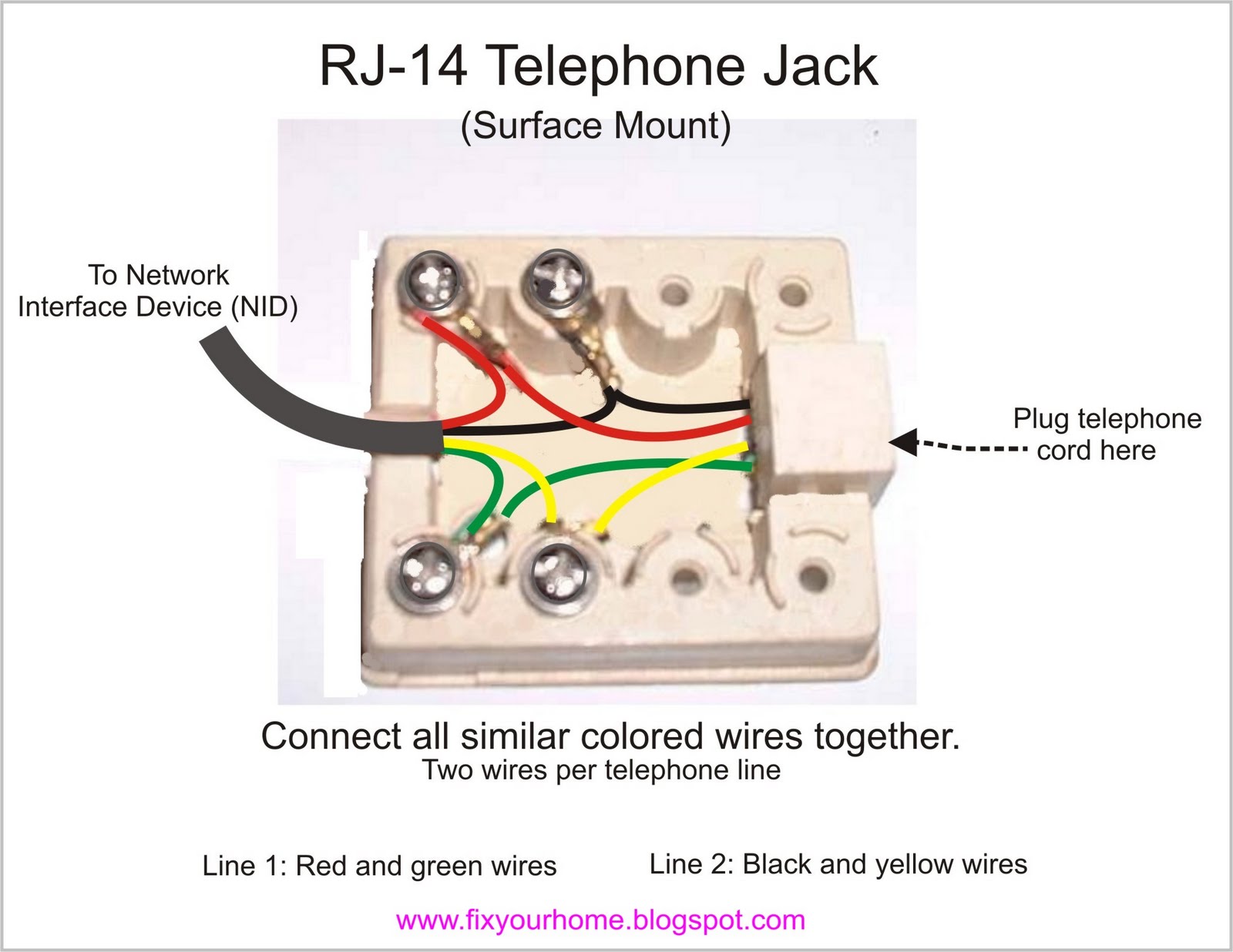
Telephone Wiring Diagrams are essential tools for understanding and visualizing the complex network of wires and connections within a telephone system. These diagrams provide a detailed layout of the wiring configuration, helping technicians troubleshoot issues, make repairs, and install new equipment efficiently.
Why Telephone Wiring Diagrams are Essential
Telephone Wiring Diagrams are crucial for several reasons:
- They provide a visual representation of the telephone system’s wiring layout.
- They help identify the location of specific components and connections within the system.
- They assist in troubleshooting electrical issues and identifying potential problems.
- They serve as a guide for installing new equipment or making modifications to the existing system.
How to Read and Interpret Telephone Wiring Diagrams
Reading and interpreting Telephone Wiring Diagrams can seem daunting at first, but with some guidance, it becomes much easier:
- Start by familiarizing yourself with the key symbols and abbreviations used in the diagram.
- Follow the flow of the wiring from one component to another, paying attention to the connections and pathways.
- Refer to the legend or key provided with the diagram to understand the meaning of each symbol or color code.
- Take your time to analyze the diagram thoroughly before attempting any repairs or modifications.
Using Telephone Wiring Diagrams for Troubleshooting
Telephone Wiring Diagrams are invaluable when it comes to troubleshooting electrical issues in a telephone system:
- Identify the specific area or component where the problem is occurring by referencing the diagram.
- Follow the wiring path to locate any potential breaks, loose connections, or other issues that may be causing the problem.
- Use the diagram to guide your repair efforts and ensure that you are addressing the root cause of the issue.
Importance of Safety
When working with electrical systems and using Wiring Diagrams, safety should always be the top priority. Here are some key safety tips and best practices:
- Always turn off the power supply before working on any electrical components.
- Use insulated tools to prevent electric shocks.
- Wear appropriate personal protective equipment, such as gloves and goggles, when handling wires and connections.
- Double-check your work and ensure all connections are secure before restoring power to the system.
Telephone Wiring Diagram
Standard Telephone Wiring Diagram

4 Wire Telephone Wiring Diagram

Telephone Handset Cord Wiring Diagram

Basic Telephone Wiring Diagram

Telephone Line RJ25, RJ14, and RJ11 Pinout Diagram, Color Codes – ETechnoG

Telephone Telephone Wire Diagrams
