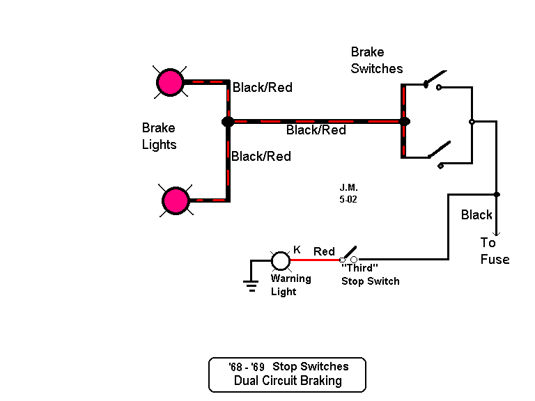
Simple Brake Light Wiring Diagrams are essential tools for understanding the electrical system of a vehicle and ensuring that the brake lights function properly. These diagrams provide a visual representation of the wiring connections and components involved in the brake light circuit.
Importance of Simple Brake Light Wiring Diagrams
- Helps to identify the correct wiring connections for the brake lights
- Aids in diagnosing and troubleshooting electrical issues related to the brake lights
- Ensures proper installation and maintenance of the brake light system
Reading and Interpreting Simple Brake Light Wiring Diagrams
When reading a Simple Brake Light Wiring Diagram, it is important to understand the symbols and color codes used to represent different components and connections. The key elements to look for in the diagram include:
- Brake light switch
- Brake light bulbs
- Wiring harnesses
- Fuses and relays
Using Simple Brake Light Wiring Diagrams for Troubleshooting
Simple Brake Light Wiring Diagrams are valuable tools for troubleshooting electrical problems related to the brake lights. By following the wiring diagram, you can pinpoint the source of the issue and determine the appropriate course of action. Some common troubleshooting steps include:
- Checking for loose or damaged connections
- Testing the brake light switch for functionality
- Inspecting the bulbs for signs of wear or damage
- Testing the fuses and relays for continuity
It is important to exercise caution when working with electrical systems and using wiring diagrams. Here are some safety tips and best practices to keep in mind:
- Always disconnect the battery before working on the electrical system
- Use insulated tools to prevent electric shock
- Avoid working on the wiring when the vehicle is running
- Follow the manufacturer’s instructions and safety guidelines
Simple Brake Light Wiring Diagram
Simple Brake Light Wiring Diagram – Wiring Schematica

Basic Brake Light Switch Wiring Diagram

Brake Light Wiring Diagram Car

Basic Brake Light Switch Wiring Diagram Collection

Basic Car Brake Light Diagram

Brake Light Wiring Schematic
