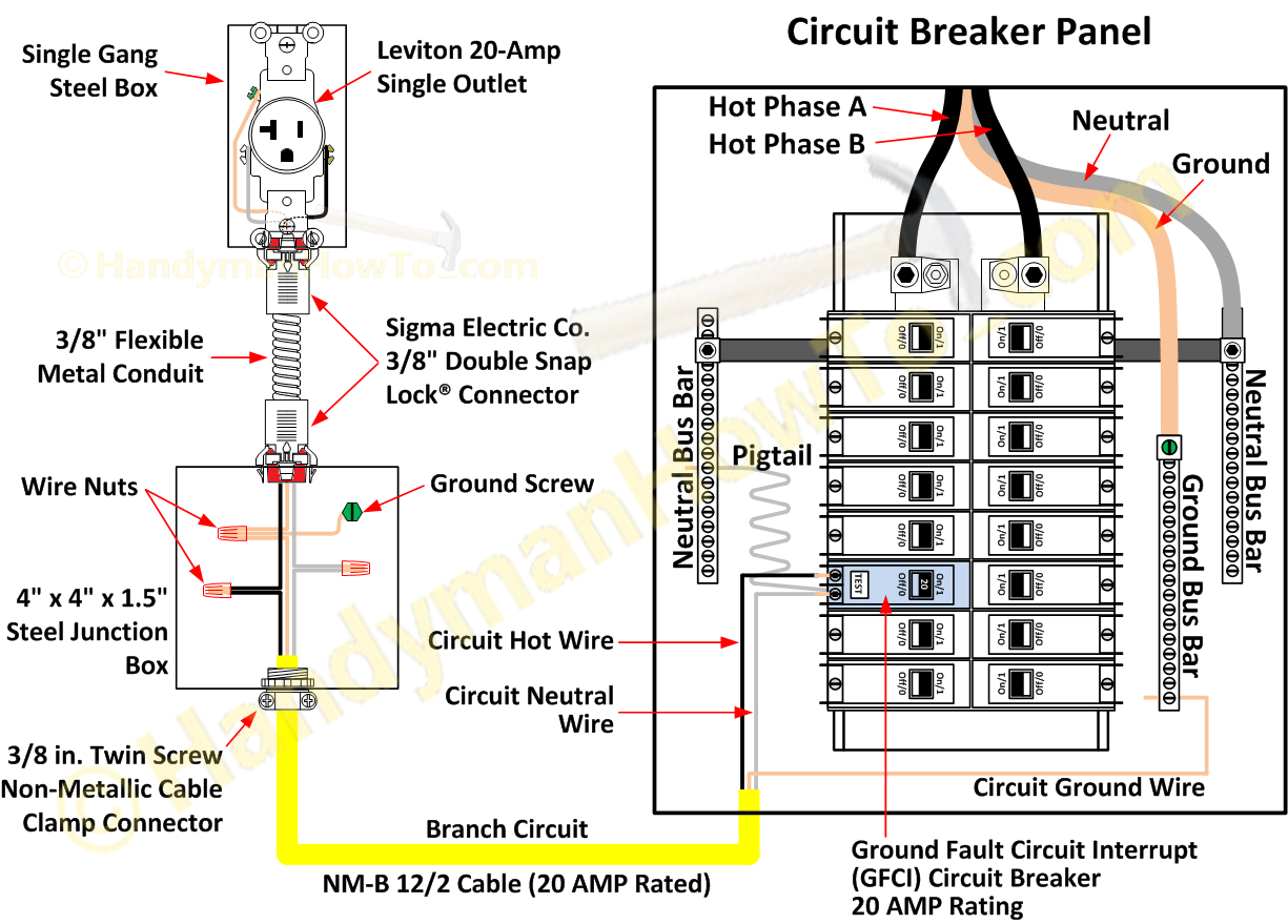
Understanding the Gfci Outlet Wiring Diagram is essential for anyone working with electrical systems in homes or commercial buildings. This diagram helps individuals identify the different components of a GFCI outlet and how they are connected to ensure proper functioning and safety. Let’s delve deeper into the importance of Gfci Outlet Wiring Diagram and how to effectively use them.
Why Gfci Outlet Wiring Diagrams are Essential
GFCI outlets are crucial for protecting individuals from electrical shocks and preventing electrical fires. The Gfci Outlet Wiring Diagram provides a visual representation of how the GFCI outlet is wired, including the connections to the line and load terminals. Understanding this diagram is essential for proper installation and troubleshooting of GFCI outlets.
How to Read and Interpret Gfci Outlet Wiring Diagram
- Identify the line and load terminals on the GFCI outlet.
- Follow the wiring diagram to connect the line terminals to the power source and load terminals to the downstream outlets or devices.
- Pay attention to the color coding of the wires to ensure correct connections.
Using Gfci Outlet Wiring Diagram for Troubleshooting Electrical Problems
When faced with electrical issues such as tripping GFCI outlets or malfunctioning circuits, the Gfci Outlet Wiring Diagram can be a valuable tool for troubleshooting. By following the diagram and checking the connections, individuals can identify any faulty wiring or components causing the problem and make necessary repairs.
Importance of Safety when Working with Electrical Systems
Working with electrical systems can be dangerous if proper safety precautions are not followed. When using Gfci Outlet Wiring Diagrams, it is important to adhere to the following safety tips:
- Always turn off the power supply before working on electrical circuits.
- Use insulated tools to prevent electric shocks.
- Double-check all connections before restoring power to the circuit.
- Seek professional help if unsure about any wiring or electrical work.
Gfci Outlet Wiring Diagram
A Comprehensive Guide To Gfci Outlet Wiring Diagrams – Wiring Diagram

How To Wire Gfci Outlet: A Step-By-Step Guide – IHSANPEDIA

120v Gfci Breaker Wiring Diagram

GFCI Outlet Wiring Diagram | EdrawMax Template

Leviton 20 Amp Gfci Wiring Diagram
