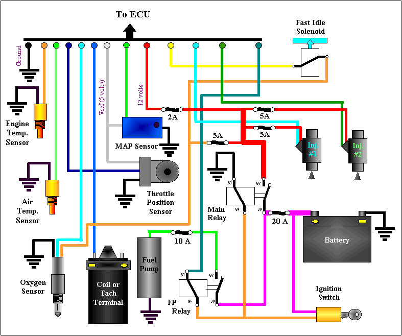
When it comes to understanding the complexities of modern vehicle systems, an Ecu Wiring Diagram is an invaluable tool for mechanics and technicians. This diagram provides a detailed schematic of the electronic control unit (ECU) wiring within a vehicle, allowing for easy identification of components and their connections.
Why Ecu Wiring Diagrams are Essential
Ecu Wiring Diagrams are essential for a number of reasons:
- They provide a visual representation of the ECU wiring, making it easier to understand the layout and connections.
- They help in diagnosing electrical issues by identifying faulty connections or components.
- They are crucial for installing aftermarket electronics or modifying the vehicle’s electrical system.
How to Read and Interpret Ecu Wiring Diagrams Effectively
Reading and interpreting Ecu Wiring Diagrams may seem daunting at first, but with practice and some basic knowledge, it can be a valuable skill:
- Start by familiarizing yourself with the legend or key that explains the symbols and colors used in the diagram.
- Follow the wiring paths to understand how components are connected and where power is supplied.
- Pay attention to grounds, power sources, and signal lines to identify potential issues.
Using Ecu Wiring Diagrams for Troubleshooting Electrical Problems
Ecu Wiring Diagrams are indispensable when it comes to troubleshooting electrical problems in a vehicle:
- Identify the affected circuit on the diagram and trace the wiring to locate potential faults.
- Check for continuity, voltage, or resistance at various points to pinpoint the issue accurately.
- Refer to the diagram to verify proper connections and component locations during repairs or installations.
Importance of Safety when Working with Ecu Wiring Diagrams
Working with electrical systems and wiring diagrams can pose safety hazards if not done correctly. Here are some safety tips and best practices to keep in mind:
- Always disconnect the battery before working on the vehicle’s electrical system to prevent short circuits or shocks.
- Use insulated tools and wear appropriate personal protective equipment (PPE) to avoid injuries during repairs.
- Double-check connections and wiring before powering up the system to prevent damage to components or fires.
Ecu Wiring Diagram
Ka24e Ecu Wiring Diagram

Ecu Nissan Wiring Diagram Color Codes – Wiring Diagram

Suzuki Jimny Ecu Wiring Diagram
2005 Nissan Maxima Ecm Wiring Diagram – Wiring Diagram and Schematic Role

Ecu Wiring Diagram – Headcontrolsystem

Engine Ecu Wiring Diagram
