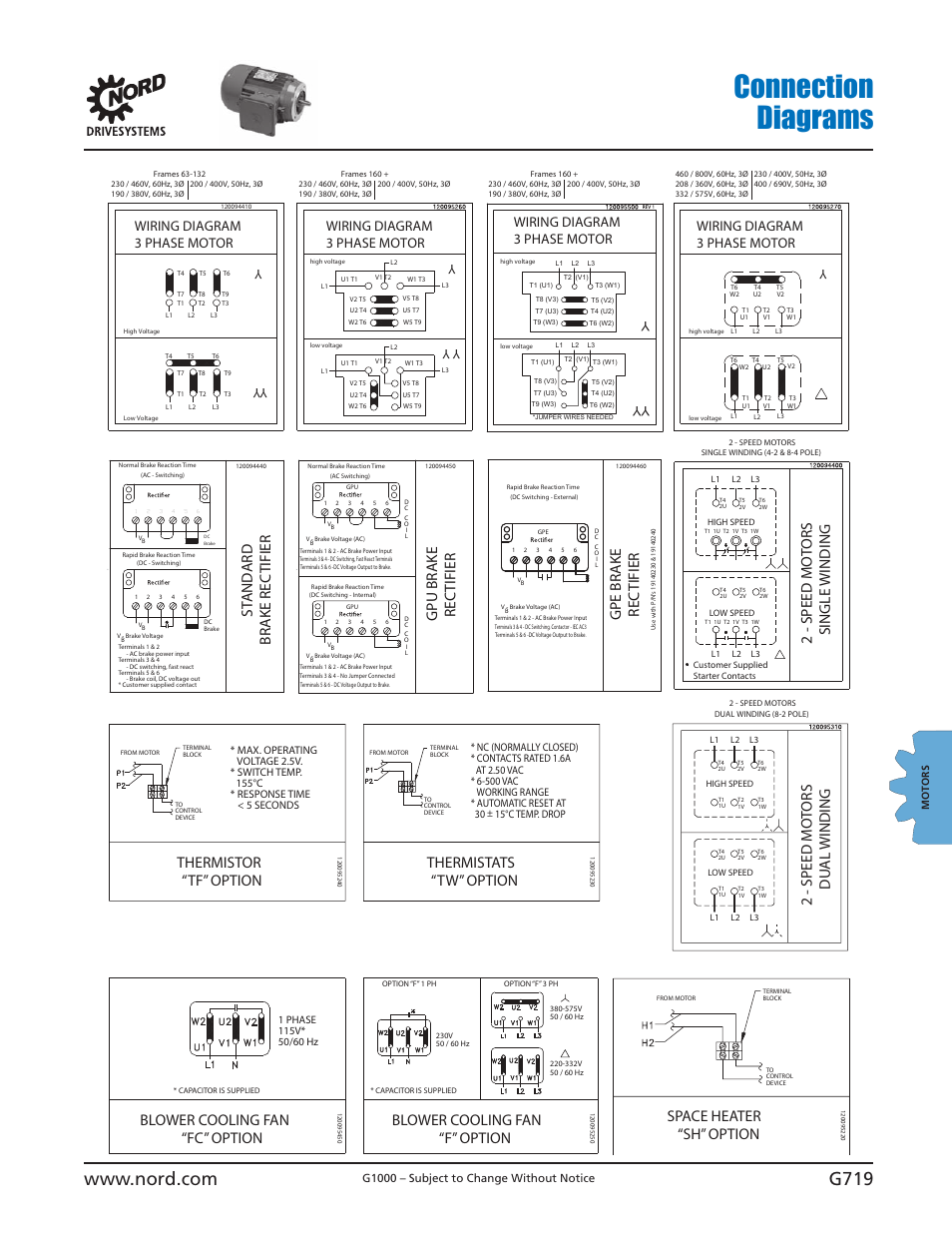
Brake Motor Wiring Diagrams are essential tools for mechanics and technicians working with electrical systems in brake motors. These diagrams provide a visual representation of the connections and wiring within the motor, helping to ensure proper installation and troubleshooting.
Why Brake Motor Wiring Diagrams are Essential
Brake Motor Wiring Diagrams are essential for the following reasons:
- Ensure proper installation of the motor
- Help identify and correct wiring errors
- Aid in troubleshooting electrical issues
- Provide a reference for future maintenance and repairs
How to Read and Interpret Brake Motor Wiring Diagrams
Reading and interpreting Brake Motor Wiring Diagrams effectively requires attention to detail and understanding of electrical symbols. Here are some tips to help:
- Identify the power source and ground connections
- Follow the lines and connections to trace the flow of electricity
- Pay attention to symbols and labels for different components
- Refer to the legend or key for explanations of symbols used
Using Brake Motor Wiring Diagrams for Troubleshooting
Brake Motor Wiring Diagrams are invaluable for troubleshooting electrical problems in brake motors. Here’s how they can help:
- Identify potential wiring issues or faulty connections
- Compare the actual wiring to the diagram to pinpoint discrepancies
- Isolate the problem area and make necessary repairs or adjustments
- Verify the correct wiring configuration after troubleshooting
Importance of Safety
Working with electrical systems and wiring diagrams requires strict adherence to safety precautions. Here are some safety tips and best practices:
- Always disconnect power before working on electrical components
- Use appropriate tools and equipment for the task
- Avoid working alone and have someone nearby in case of emergency
- Follow manufacturer’s instructions and guidelines for handling electrical systems
Brake Motor Wiring Diagram
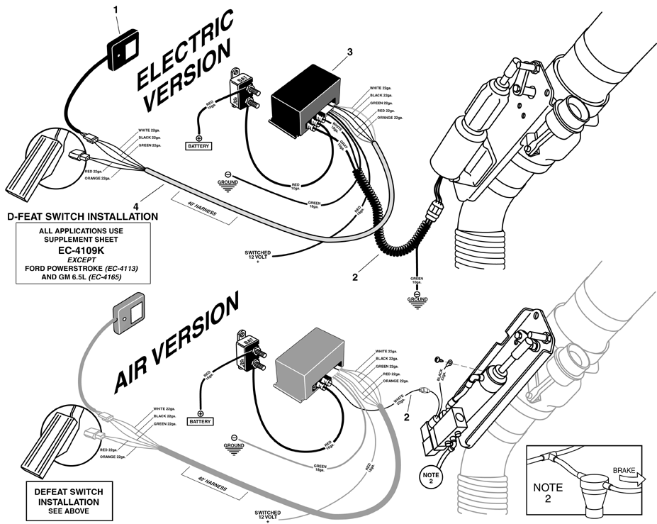
Engine Brake Wiring Diagram – Wiring Diagram and Schematics

Clutch Brake Motor Connection Diagram Rectifier Module – YouTube

Motor brake rectifier connection diagram | Engineers CommonRoom

Nord Brake Motor Wiring Diagram – Coearth

Engine Brake Wiring Diagram – Wiring Diagram and Schematics
