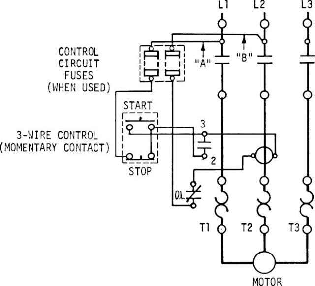
Basic Start Stop Wiring Diagrams are fundamental tools used in the electrical industry to illustrate the control circuit of starting and stopping an electric motor or other device. These diagrams provide a visual representation of the connections between various components, allowing technicians and electricians to understand how the system operates.
Importance of Basic Start Stop Wiring Diagrams
Understanding Basic Start Stop Wiring Diagrams is essential for various reasons:
- Helps in troubleshooting electrical issues
- Ensures proper installation and maintenance of electrical systems
- Provides a clear understanding of the control circuit
How to Read and Interpret Basic Start Stop Wiring Diagrams
When looking at a Basic Start Stop Wiring Diagram, it is important to pay attention to the following key components:
- Power supply: Understand where the power is coming from and how it is distributed
- Start and stop buttons: Identify the locations of these components and how they are connected
- Motor: Determine how the motor is connected in the circuit
Using Basic Start Stop Wiring Diagrams for Troubleshooting
Basic Start Stop Wiring Diagrams are invaluable tools when troubleshooting electrical problems. By following the diagram, technicians can identify the root cause of the issue and make the necessary repairs or adjustments. Some common troubleshooting steps include:
- Checking for loose connections
- Testing components for continuity
- Verifying proper voltage levels
Importance of Safety
When working with electrical systems and using Basic Start Stop Wiring Diagrams, safety should always be the top priority. Here are some safety tips and best practices to keep in mind:
- Always turn off the power supply before working on any electrical components
- Use insulated tools to prevent electric shock
- Wear appropriate personal protective equipment, such as gloves and goggles
- Follow proper lockout/tagout procedures to prevent accidental energization
Basic Start Stop Wiring Diagram
Start Stop Circuit – What They Are, Where They Are Used And How To Wire

The Essential Guide to Start-stop Diagram – RAYPCB

Start Stop Circuit Diagram
Basic Start/Stop AC Motor Control Schematics under Repository-circuits

Start Stop Wiring Diagram

Basic Start Stop Circuit Diagram
